
Материал из Википедии — свободной энциклопедии
| М-71 | |
| Завод № 19 (Молотов) | |
| 1939—1943 | |
| 18-цилиндровый двухрядный звездообразный, редукторный | |
| Технические характеристики | |
| 59,7 л | |
| в зависимости от модификации от 1500/2000 лс до 1850/2200 лс | |
| 155,5 мм | |
| 174,5 мм | |
| 18 | |
| ПЦН | |
| в зависимости от модификации | |
| карбюратор | |
| воздушного охлаждения | |
| Размеры | |
| 1380 мм | |
| в зависимости от модификации | |
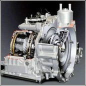
М-71 — советский авиационный двухрядный звездообразный 18-цилиндровый двигатель, спроектированный в ОКБ А. Д. Швецова.
В 1933 году СССР заключил с фирмой «Райт» (США) соглашение о производстве 9-цилиндрового американского звездообразного двигателя Райт «Циклон» R-1820. Освоение двигателя поручили новому заводу № 19 в Перми. К 1934 году двигатель «Циклон» уже не являлся новинкой и для усовершенствования двигателя при заводе № 19 был организован конструкторский отдел. Главным конструктором назначили А. Д. Швецова. Двигатель постоянно усовершенствовался, всё больше удаляясь от прототипа. С 1937 года разрабатывался двигатель М-70 — 18-цилиндровый мотор на базе М-25. Дальнейшим развитием М-70, уже на базе узлов М-63, стал двигатель М-71.
В 1939 году были изготовлены 4 экземпляра М-71 для проведения стендовых испытаний. Процесс доводки двигателя занял много времени. Он выдержал государственные испытания осенью 1942, но в большую серию не запускался.
ru.bywiki.com
Материал из Википедии — свободной энциклопедии
| М-71 | |
| Завод № 19 (Молотов) | |
| 1939—1943 | |
| 18-цилиндровый двухрядный звездообразный, редукторный | |
| Технические характеристики | |
| 59,7 л | |
| в зависимости от модификации от 1500/2000 лс до 1850/2200 лс | |
| 155,5 мм | |
| 174,5 мм | |
| 18 | |
| ПЦН | |
| в зависимости от модификации | |
| карбюратор | |
| воздушного охлаждения | |
| Размеры | |
| 1380 мм | |
| в зависимости от модификации | |
М-71 — советский авиационный двухрядный звездообразный 18-цилиндровый двигатель, спроектированный в ОКБ А. Д. Швецова.
В 1933 году СССР заключил с фирмой «Райт» (США) соглашение о производстве 9-цилиндрового американского звездообразного двигателя Райт «Циклон» R-1820. Освоение двигателя поручили новому заводу № 19 в Перми. К 1934 году двигатель «Циклон» уже не являлся новинкой и для усовершенствования двигателя при заводе № 19 был организован конструкторский отдел. Главным конструктором назначили А. Д. Швецова. Двигатель постоянно усовершенствовался, всё больше удаляясь от прототипа. С 1937 года разрабатывался двигатель М-70 — 18-цилиндровый мотор на базе М-25. Дальнейшим развитием М-70, уже на базе узлов М-63, стал двигатель М-71.
В 1939 году были изготовлены 4 экземпляра М-71 для проведения стендовых испытаний. Процесс доводки двигателя занял много времени. Он выдержал государственные испытания осенью 1942, но в большую серию не запускался.
Двигатель М-71 представлял собой 18-цилиндровый двухрядный звездообразный четырёхтактный поршневой двигатель воздушного охлаждения и являлся «удвоенным» М-63.
В конструкции широко использовались узлы М-63. Коленчатый вал выполнен с двумя противовесами.
Существовали следующие модификации двигателя.
Двигатель М-71 устанавливался на опытных самолётах:
ru.wikiyy.com
Материал из Википедии — свободной энциклопедии
| М-71 | |
| Завод № 19 (Молотов) | |
| 1939—1943 | |
| 18-цилиндровый двухрядный звездообразный, редукторный | |
| Технические характеристики | |
| 59,7 л | |
| в зависимости от модификации от 1500/2000 лс до 1850/2200 лс | |
| 155,5 мм | |
| 174,5 мм | |
| 18 | |
| ПЦН | |
| в зависимости от модификации | |
| карбюратор | |
| воздушного охлаждения | |
| Размеры | |
| 1380 мм | |
| в зависимости от модификации | |
М-71 — советский авиационный двухрядный звездообразный 18-цилиндровый двигатель, спроектированный в ОКБ А. Д. Швецова.
В 1933 году СССР заключил с фирмой «Райт» (США) соглашение о производстве 9-цилиндрового американского звездообразного двигателя Райт «Циклон» R-1820. Освоение двигателя поручили новому заводу № 19 в Перми. К 1934 году двигатель «Циклон» уже не являлся новинкой и для усовершенствования двигателя при заводе № 19 был организован конструкторский отдел. Главным конструктором назначили А. Д. Швецова. Двигатель постоянно усовершенствовался, всё больше удаляясь от прототипа. С 1937 года разрабатывался двигатель М-70 — 18-цилиндровый мотор на базе М-25. Дальнейшим развитием М-70, уже на базе узлов М-63, стал двигатель М-71.
В 1939 году были изготовлены 4 экземпляра М-71 для проведения стендовых испытаний. Процесс доводки двигателя занял много времени. Он выдержал государственные испытания осенью 1942, но в большую серию не запускался.
Двигатель М-71 представлял собой 18-цилиндровый двухрядный звездообразный четырёхтактный поршневой двигатель воздушного охлаждения и являлся «удвоенным» М-63.
В конструкции широко использовались узлы М-63. Коленчатый вал выполнен с двумя противовесами.
Существовали следующие модификации двигателя.
Двигатель М-71 устанавливался на опытных самолётах:
ru.wikipedia.org.mevn.net
1. Пермь – Perm is a city and the administrative center of Perm Krai, Russia, located on the banks of the Kama River in the European part of Russia near the Ural Mountains. According to the 2010 Census, Perms population is 991,162, as of the 2010 Census, the city was the thirteenth most populous in Russia. From 1940 to 1957 it was named Molotov, the name Perm is of Finno-Ugric etymology, likely of Uralic origin. Komi is a member of the Permic group of Finno-Ugric languages, in Finnish and Vepsian perämaa means far-away land, similarly, in Hungarian perem means edge or verge. The geologic period of the Permian takes its name from the toponym, the city is located on the bank of the Kama River upon hilly terrain. The Kama is the tributary of the Volga River and one of the deepest and most picturesque rivers of Russia. This river is the waterway which grants the Ural Mountains access to the White Sea, Baltic Sea, Sea of Azov, Black Sea, the Kama divides the city into two parts, the central part and the right bank part. The city stretches for 70 kilometers along the Kama and 40 kilometers across it, the city street grid parallels the Kama River, traveling generally east-west, while other main streets run perpendicularly to those following the river. The grid pattern accommodates the hills of the city where it crosses them, another distinguishing feature of the citys relief is the large quantity of small rivers and brooks. The largest of them are the Mulyanka, the Yegoshikha, the Motovilikha, Perm has a continental climate with warm summers and long, cold winters. Perm is located in the old Perman area, which was inhabited by Finno-Ugric peoples. Perm was first mentioned as the village of Yagoshikha in 1647, however, vasily Tatishchev, appointed by the Tsar as a chief manager of Ural factories, founded Perm together with another major center of the Ural region, Yekaterinburg. In 1870, a theater was opened in the city. In 1916, Perm State University—a major educational institution in modern Russia—was opened, after the outbreak of the Russian Civil War, Perm became a prime target for both sides because of its military munitions factories. On December 25,1918, the Siberian White Army under Anatoly Pepelyayev, on July 1,1919, the city was retaken by the Red Army. In the 1930s, Perm grew as an industrial city with aviation, shipbuilding. During the Great Patriotic War, Perm was a center of artillery production in the Soviet Union. During the cold war, Perm became a closed city, the city is a major administrative, industrial, scientific, and cultural center
2. Компрессор – A gas compressor is a mechanical device that increases the pressure of a gas by reducing its volume. An air compressor is a type of gas compressor. Compressors are similar to pumps, both increase the pressure on a fluid and both can transport the fluid through a pipe, as gases are compressible, the compressor also reduces the volume of a gas. Liquids are relatively incompressible, while some can be compressed, the action of a pump is to pressurize. The main types of gas compressors are illustrated and discussed below and they can be either stationary or portable, can be single or multi-staged, and can be driven by electric motors or internal combustion engines. Small reciprocating compressors from 5 to 30 horsepower are commonly seen in applications and are typically for intermittent duty. Larger reciprocating compressors well over 1,000 hp are commonly found in large industrial, discharge pressures can range from low pressure to very high pressure. Another type of reciprocating compressor is the swash plate compressor, which uses pistons moved by a swash plate mounted on a shaft, household, home workshop, and smaller job site compressors are typically reciprocating compressors 1½ hp or less with an attached receiver tank. Rotary screw compressors use two meshed rotating positive-displacement helical screws to force the gas into a smaller space and these are usually used for continuous operation in commercial and industrial applications and may be either stationary or portable. Their application can be from 3 horsepower to over 1,200 horsepower, rotary screw compressors are commercially produced in Oil Flooded, Water Flooded and Dry type. The efficiency of rotary compressors depends on the air drier, rotary vane compressors consist of a rotor with a number of blades inserted in radial slots in the rotor. The rotor is mounted offset in a housing that is either circular or a more complex shape. As the rotor turns, blades slide in and out of the slots keeping contact with the wall of the housing. Thus, a series of increasing and decreasing volumes is created by the rotating blades, rotary Vane compressors are, with piston compressors one of the oldest of compressor technologies. With suitable port connections, the devices may be either a compressor or a vacuum pump and they can be either stationary or portable, can be single or multi-staged, and can be driven by electric motors or internal combustion engines. A rotary vane compressor is well suited to electric drive and is significantly quieter in operation than the equivalent piston compressor. Rotary vane compressors can have mechanical efficiencies of about 90%, rolling piston forces gas against a stationary vane. A scroll compressor, also known as pump and scroll vacuum pump
3. Турбонаддув – Turbochargers were originally known as turbosuperchargers when all forced induction devices were classified as superchargers. Nowadays the term supercharger is usually applied only to mechanically driven forced induction devices, compared to a mechanically driven supercharger, turbochargers tend to be more efficient, but less responsive. Twincharger refers to an engine with both a supercharger and a turbocharger, turbochargers are commonly used on truck, car, train, aircraft, and construction equipment engines. They are most often used with Otto cycle and Diesel cycle internal combustion engines and they have also been found useful in automotive fuel cells. Forced induction dates from the late 19th century, when Gottlieb Daimler patented the technique of using a pump to force air into an internal combustion engine in 1885. During World War I French engineer Auguste Rateau fitted turbochargers to Renault engines powering various French fighters with some success, in 1918, General Electric engineer Sanford Alexander Moss attached a turbocharger to a V12 Liberty aircraft engine. Turbochargers were first used in aircraft engines such as the Napier Lioness in the 1920s. Ships and locomotives equipped with turbocharged diesel engines began appearing in the 1920s, turbochargers were also used in aviation, most widely used by the United States. During World War II, notable examples of U. S. aircraft with turbochargers include the B-17 Flying Fortress, B-24 Liberator, P-38 Lightning, and P-47 Thunderbolt. Turbochargers are widely used in car and commercial vehicles because they allow smaller-capacity engines to have improved fuel economy, reduced emissions, higher power, in contrast to turbochargers, superchargers are mechanically driven by the engine. Belts, chains, shafts, and gears are common methods of powering a supercharger, for example, on the single-stage single-speed supercharged Rolls-Royce Merlin engine, the supercharger uses about 150 horsepower. Yet the benefits outweigh the costs, for the 150 hp to drive the supercharger the engine generates an additional 400-horsepower, a net gain of 250 hp. This is where the principal disadvantage of a supercharger becomes apparent, another disadvantage of some superchargers is lower adiabatic efficiency as compared to turbochargers. Adiabatic efficiency is a measure of an ability to compress air without adding excess heat to that air. Even under ideal conditions, the compression process always results in elevated temperature, however. Roots superchargers impart significantly more heat to the air than turbochargers, thus, for a given volume and pressure of air, the turbocharged air is cooler, and as a result denser, containing more oxygen molecules, and therefore more potential power than the supercharged air. In practical application the disparity between the two can be dramatic, with turbochargers often producing 15% to 30% more power based solely on the differences in adiabatic efficiency. By comparison, a turbocharger does not place a direct mechanical load on the engine, although turbochargers place exhaust back pressure on engines, in contrast to supercharging, the primary disadvantage of turbocharging is what is referred to as lag or spool time
4. Цилиндр (двигатель) – A cylinder is the central working part of a reciprocating engine or pump, the space in which a piston travels. Multiple cylinders are arranged side by side in a bank, or engine block. Cylinders may be sleeved or sleeveless, a sleeveless engine may also be referred to as a parent-bore engine. A cylinders displacement, or swept volume, can be calculated by multiplying its cross-sectional area by the distance the piston travels within the cylinder, the engine displacement can be calculated by multiplying the swept volume of one cylinder by the number of cylinders. The rings make near contact with the walls, riding on a thin layer of lubricating oil. The first illustration depicts a longitudinal section of a cylinder in a steam engine, the sliding part at the bottom is the piston, and the upper sliding part is a distribution valve that directs steam alternately into either end of the cylinder. Refrigerator and air compressors are heat engines driven in reverse cycle as pumps. Internal combustion engines operate on the inherent volume change accompanying oxidation of gasoline, diesel fuel or ethanol and they are not classical heat engines since they expel the working substance, which is also the combustion product, into the surroundings. The reciprocating motion of the pistons is translated into crankshaft rotation via connecting rods, as a piston moves back and forth, a connecting rod changes its angle, its distal end has a rotating link to the crankshaft. A typical four-cylinder automobile engine has a row of water-cooled cylinders. V engines use two angled cylinder banks, the V configuration is utilized to create a more compact configuration relative to the number of cylinders. For example, there are also rotary turbines, the Wankel engine is a rotary adaptation of the cylinder-piston concept which has been used by Mazda and NSU in automobiles. Rotary engines are relatively quiet because they lack the clatter of reciprocating motion, air-cooled engines generally use individual cases for the cylinders to facilitate cooling. Inline motorcycle engines are an exception, having two-, three-, four-, water-cooled engines with only a few cylinders may also use individual cylinder cases, though this makes the cooling system more complex. The Ducati motorcycle company, which for years used air-cooled motors with individual cylinder cases, in some engines, especially French designs, the cylinders have wet liners. They are formed separately from the casting so that liquid coolant is free to flow around their outsides. Wet-lined cylinders have cooling and a more even temperature distribution. During use, the cylinder is subject to wear from the action of the piston rings
5. Звездообразный двигатель – The radial engine is a reciprocating type internal combustion engine configuration in which the cylinders radiate outward from a central crankcase like the spokes of a wheel. It resembles a star when viewed from the front, and is called a star engine in some languages. The radial configuration was very commonly used for aircraft engines before gas turbine engines became predominant, instead, the pistons are connected to the crankshaft with a master-and-articulating-rod assembly. One piston, the uppermost one in the animation, has a rod with a direct attachment to the crankshaft. The remaining pistons pin their connecting rods attachments to rings around the edge of the master rod, extra rows of radial cylinders can be added in order to increase the capacity of the engine without adding to its diameter. Four-stroke radials have an odd number of cylinders per row, so that a consistent every-other-piston firing order can be maintained, for example, on a five-cylinder engine the firing order is 1,3,5,2,4 and back to cylinder 1. Moreover, this leaves a one-piston gap between the piston on its combustion stroke and the piston on compression. The active stroke directly helps compress the next cylinder to fire, if an even number of cylinders were used, an equally timed firing cycle would not be feasible. The radial engine normally uses fewer cam lobes than other types, as with most four-strokes, the crankshaft takes two revolutions to complete the four strokes of each piston. The camshaft ring is geared to spin slower and in the direction to the crankshaft. The cam lobes are placed in two rows for the intake and exhaust, for the example, four cam lobes serve all five cylinders, whereas 10 would be required for a typical inline engine with the same number of cylinders and valves. C. M. Manly constructed a water-cooled five-cylinder radial engine in 1901, manlys engine produced 52 hp at 950 rpm. This was installed in his triplane and made a number of short free-flight hops, another early radial engine was the three-cylinder Anzani, originally built as a W3 fan configuration, one of which powered Louis Blériots Blériot XI across the English Channel. Georges Canton and Pierre Unné patented the engine design in 1909, offering it to the Salmson company. It was similar in concept to the radial, the main difference being that the propeller was bolted to the engine. The problem of the cooling of the cylinders, a factor with the early stationary radials, was alleviated by the engine generating its own cooling airflow. Most German aircraft of the time used water-cooled inline 6-cylinder engines, in the early 1920s Le Rhône converted a number of their rotary engines into stationary radial engines. By 1918 the potential advantages of air-cooled radials over the inline engine
6. Четырёхтактный двигатель – A four-stroke engine is an internal combustion engine in which the piston completes four separate strokes while turning a crankshaft. A stroke refers to the travel of the piston along the cylinder. The four separate strokes are termed, Intake, also known as induction or suction This stroke of the piston begins at top dead center and ends at bottom dead center. In this stroke the valve must be in the open position while the piston pulls an air-fuel mixture into the cylinder by producing vacuum pressure into the cylinder through its downward motion. Compression, This stroke begins at B. D. C, or just at the end of the suction stroke, in this stroke the piston compresses the air-fuel mixture in preparation for ignition during the power stroke. Both the intake and exhaust valves are closed during this stage, combustion, also known as power or ignition This is the start of the second revolution of the four stroke cycle. At this point the crankshaft has completed a full 360 degree revolution, while the piston is at T. D. C. The compressed air-fuel mixture is ignited by a plug or by heat generated by high compression. This stroke produces mechanical work from the engine to turn the crankshaft, during the exhaust stroke, the piston once again returns from B. D. C. to T. D. C. While the exhaust valve is open and this action expels the spent air-fuel mixture through the exhaust valve. Nikolaus August Otto as a man was a traveling salesman for a grocery concern. In his travels he encountered the internal combustion engine built in Paris by Belgian expatriate Jean Joseph Etienne Lenoir, in 1860, Lenoir successfully created a double-acting engine that ran on illuminating gas at 4% efficiency. The 18 litre Lenoir Engine produced only 2 horsepower, the Lenoir engine ran on illuminating gas made from coal, which had been developed in Paris by Philip Lebon. In testing a replica of the Lenoir engine in 1861 Otto became aware of the effects of compression on the fuel charge, in 1862, Otto attempted to produce an engine to improve on the poor efficiency and reliability of the Lenoir engine. He tried to create an engine that would compress the fuel prior to ignition. Many other engineers were trying to solve the problem, with no success, in 1864, Otto and Eugen Langen founded the first internal combustion engine production company, NA Otto and Cie. Otto and Cie succeeded in creating an atmospheric engine that same year. The factory ran out of space and was moved to the town of Deutz, in 1872, Gottlieb Daimler was technical director and Wilhelm Maybach was the head of engine design
7. Поршневой двигатель внутреннего сгорания – A reciprocating engine, also often known as a piston engine, is typically a heat engine that uses one or more reciprocating pistons to convert pressure into a rotating motion. This article describes the features of all types. The main types are, the combustion engine, used extensively in motor vehicles, the steam engine, the mainstay of the Industrial Revolution. There may be one or more pistons, the hot gases expand, pushing the piston to the bottom of the cylinder. This position is known as the Bottom Dead Center, or where the piston forms the largest volume in the cylinder. The piston is returned to the top by a flywheel. This is where the forms the smallest volume in the cylinder. In most types the expanded or exhausted gases are removed from the cylinder by this stroke, the exception is the Stirling engine, which repeatedly heats and cools the same sealed quantity of gas. The stroke is simply the distance between the TDC and the BDC, or the greatest distance that the piston can travel in one direction, in some designs the piston may be powered in both directions in the cylinder, in which case it is said to be double-acting. In most types, the movement of the piston is converted to a rotating movement via a connecting rod. A flywheel is used to ensure smooth rotation or to store energy to carry the engine through an un-powered part of the cycle. The more cylinders an engine has, generally, the more vibration-free it can operate. The power of an engine is proportional to the volume of the combined pistons displacement. A seal must be made between the piston and the walls of the cylinder so that the high pressure gas above the piston does not leak past it. This seal is provided by one or more piston rings. These are rings made of a metal, and are sprung into a circular groove in the piston head. The rings fit tightly in the groove and press against the wall to form a seal. Cylinder capacities may range from 10 cm³ or less in model engines up to several thousand cubic centimetres in ships engines, the compression ratio affects the performance in most types of reciprocating engine
8. Система охлаждения двигателя внутреннего сгорания – Internal combustion engine cooling uses either air or a liquid to remove the waste heat from an internal combustion engine. For small or special purpose engines, air cooling makes for a lightweight, the more complex circulating liquid-cooled engines also ultimately reject waste heat to the air, but circulating liquid improves heat transfer from internal parts of the engine. Engines for watercraft may use open-loop cooling, but air and surface vehicles must recirculate a fixed volume of liquid, heat engines generate mechanical power by extracting energy from heat flows, much as a water wheel extracts mechanical power from a flow of mass falling through a distance. Engines are inefficient, so more heat energy enters the engine comes out as mechanical power. Internal combustion engines remove waste heat through cool intake air, hot exhaust gases, Engines with higher efficiency have more energy leave as mechanical motion and less as waste heat. Some waste heat is essential, it guides heat through the engine, much as a water wheel works only if there is some exit velocity in the water to carry it away. Thus, all heat engines need cooling to operate, Cooling is also needed because high temperatures damage engine materials and lubricants. Cooling becomes more important in when the climate very hot. Internal-combustion engines burn fuel hotter than the temperature of engine materials. Engine cooling removes energy fast enough to keep temperatures low so the engine can survive, some high-efficiency engines run without explicit cooling and with only incidental heat loss, a design called adiabatic. Such engines can achieve high efficiency but compromise power output, duty cycle, engine weight, durability, most internal combustion engines are fluid cooled using either air or a liquid coolant run through a heat exchanger cooled by air. Marine engines and some engines have ready access to a large volume of water at a suitable temperature. The water may be used directly to cool the engine, but often has sediment, which can clog coolant passages, or chemicals, such as salt, thus, engine coolant may be run through a heat exchanger that is cooled by the body of water. Most liquid-cooled engines use a mixture of water and chemicals such as antifreeze, the industry term for the antifreeze mixture is engine coolant. Some antifreezes use no water at all, instead using a liquid with different properties, such as propylene glycol or a combination of propylene glycol, most air-cooled engines use some liquid oil cooling, to maintain acceptable temperatures for both critical engine parts and the oil itself. Most liquid-cooled engines use air cooling, with the intake stroke of air cooling the combustion chamber. An exception is Wankel engines, where parts of the combustion chamber are never cooled by intake. There are many demands on a cooling system, one key requirement is to adequately serve the entire engine, as the whole engine fails if just one part overheats
9. И-185 – The Polikarpov I-185 was a Soviet fighter aircraft designed in 1940. It was flown with three engines but all of them were either insufficiently developed for use or their full production was reserved for other fighters already in production. The I-185 program was cancelled on 27 January 1943, the I-185, designed in early 1940, was based on the I-180, which was itself a development of the I-16, but was virtually a new design. The monocoque fuselage was built of shpon, molded birch plywood, and also had an integral fin. The two-spar, all-metal wing was smaller and thinner than the I-180s wing, nearly as thin as that of the Supermarine Spitfires wing at 13% at the root, the wing had a NACA-230 profile and was skinned in duralumin. Pneumatically powered split flaps and leading edge slats were fitted, the outer wing panels had 3° of dihedral. The fabric-covered control surfaces were framed in duralumin, the protected 540-litre fuel tanks were mounted between the wing center section spars. The I-185 used an undercarriage with a retractable tailwheel. The unproven 1,492 kW 18-cylinder, two-row Tumansky M-90 radial engine was carried on welded steel tubes and it was fitted with a ducted spinner to improve cooling with the air expelled through gills as in the I-180 to provide additional thrust. The synchronized armament was mounted in the fuselage, two 7.62 mm ShKAS machine guns and two 12.7 mm Berezin UBS machine guns, a 500-kilogram bomb could be carried under overload conditions. The first prototype was completed in May 1940, but the only example of the M-90 did not provide enough power for take-off. The prototype was modified to use another engine, the 895-kilowatt Shvetsov M-81 radial. The I-185 finally took to the air on January 11,1941, a second prototype was completed at the end of 1940 with a 14-cylinder,1,268 kW Shvetsov M-82A radial engine. The forward fuselage had to be redesigned to accommodate the slimmer engine, the drawings for this engine installation was passed to Lavochkin and Yakovlev where they proved very useful in designing their own fighters using the M-82 engine, notably the Lavochkin La-5. A third prototype was built that used the larger and heavier Shvetsov M-71 radial engine of 1,492 kW. It was recommended for production, even before it began combat trials in November 1942. All three aircraft were assigned to the 728th Fighter Aviation Regiment of the 3rd Air Army of the Kalinin Front and were controlled to prevent the loss of the prototypes. For example, all sorties had to be flown over Soviet-controlled territory, pilots reports were quite enthusiastic, the 728ths commander, Captain Vasilyaka wrote, The I-185 outclasses both Soviet and foreign aircraft in level speed
10. Су-6 – The Sukhoi Su-6 was a Soviet ground attack aircraft developed during World War II. The mixed-power high-altitude interceptor Su-7 was based on the single-seat Su-6 prototype, development of the Su-6 began in 1939, when the Sukhoi design bureau began work on a single-seat armoured ground-attack aircraft. An order for two prototypes was placed on 4 March 1940, and on 1 March 1941 flight testing of the first prototype was begun by test pilot A. I. The second prototype flew only in January 1942 because the OKB had to be evacuated after the start of the Great Patriotic War and it was armed with two 23 mm cannon, four machine guns and ten rails for aerial rockets. Test results were favorable, and the AFRA Scientific Research Institute recommended the acquisition of a small production batch for testing under front-line conditions. A draft resolution for the production of 25 aircraft was prepared, however unfortunately for Sukhoi, meanwhile, combat experience with single-seat Il-2s demonstrated the need for a rear gunner. The third prototype was designed with the second crewman at the expense of bomb load. Official tests revealed that the two-seat Su-6 had a 100 km/h greater top speed than the Il-2, when the troublesome M-71 was canceled, Sukhoi was directed to utilize the liquid-cooled Mikulin AM-42 engine. Although the Su-6 never entered production, in 1943 Pavel Sukhoi was awarded the Stalin Prize of the 1st Degree for the development of the aircraft, as an experiment, the basic single-seat Su-6 design was converted into a mixed-power high-altitude interceptor named Su-7. The armor was removed and the fuselage was of all-metal construction, power came from a Shvetsov ASh-82FN piston engine with two TK-3 turbochargers in the nose and a Glushko RD-1-KhZ rocket engine in the tail. The piston engine produced 1,380 kW, while the rocket engine utilized kerosene and nitric acid for fuel, armament consisted of three 20 mm ShVAK cannon with 370 rounds of ammunition. The sole Su-7 was completed in 1944, test flights demonstrated a top speed of 510 km/h at 12,000 m without the rocket motor, and 705 km/h with the rocket. In 1945, the rocket exploded during flight testing, killing the pilot. A The initial design for the Su-6, S The second prototype with various modifications. SA The SA with 2 x OKB-16 37mm Cannon and 2x ShKAS7.62 mm machine-guns, s2A The Su-6 fitted with a second cockpit with rear wards firing machine-gun. Testing revealed better performance and armour than the Il-2, but despite recommendations, production was not carried out due to the M-71 engine not enterring production
wikivisually.com
Материал из Википедии — свободной энциклопедии
| М-71 | |
| Завод № 19 (Молотов) | |
| 1939—1943 | |
| 18-цилиндровый двухрядный звездообразный, редукторный | |
| Технические характеристики | |
| 59,7 л | |
| в зависимости от модификации от 1500/2000 лс до 1850/2200 лс | |
| 155,5 мм | |
| 174,5 мм | |
| 18 | |
| ПЦН | |
| в зависимости от модификации | |
| карбюратор | |
| воздушного охлаждения | |
| Размеры | |
| 1380 мм | |
| в зависимости от модификации | |
М-71 — советский авиационный двухрядный звездообразный 18-цилиндровый двигатель, спроектированный в ОКБ А. Д. Швецова.
В 1933 году СССР заключил с фирмой «Райт» (США) соглашение о производстве 9-цилиндрового американского звездообразного двигателя Райт «Циклон» R-1820. Освоение двигателя поручили новому заводу № 19 в Перми. К 1934 году двигатель «Циклон» уже не являлся новинкой и для усовершенствования двигателя при заводе № 19 был организован конструкторский отдел. Главным конструктором назначили А. Д. Швецова. Двигатель постоянно усовершенствовался, всё больше удаляясь от прототипа. С 1937 года разрабатывался двигатель М-70 — 18-цилиндровый мотор на базе М-25. Дальнейшим развитием М-70, уже на базе узлов М-63, стал двигатель М-71.
В 1939 году были изготовлены 4 экземпляра М-71 для проведения стендовых испытаний. Процесс доводки двигателя занял много времени. Он выдержал государственные испытания осенью 1942, но в большую серию не запускался.
Двигатель М-71 представлял собой 18-цилиндровый двухрядный звездообразный четырёхтактный поршневой двигатель воздушного охлаждения и являлся «удвоенным» М-63.
В конструкции широко использовались узлы М-63. Коленчатый вал выполнен с двумя противовесами.
Существовали следующие модификации двигателя.
Двигатель М-71 устанавливался на опытных самолётах:
encyclopaedia.bid
| М-71 | |
| Завод № 19 (Молотов) | |
| 1939—1943 | |
| 18-цилиндровый двухрядный звездообразный, редукторный | |
| Технические характеристики | |
| 59,7 л | |
| в зависимости от модификации от 1500/2000 лс до 1850/2200 лс | |
| 174,5 мм | |
| 18 | |
| 155,5 мм | |
| ПЦН | |
| в зависимости от модификации | |
| карбюратор | |
| воздушного охлаждения | |
| Размеры | |
| в зависимости от модификации | |
М-71 — советский авиационный двухрядный звездообразный 18-цилиндровый двигатель, спроектированный в ОКБ А. Д. Швецова.
В 1933 году СССР заключил с фирмой «Райт» (США) соглашение о производстве 9-цилиндрового американского звездообразного двигателя Райт «Циклон» R-1820.
Освоение двигателя поручили новому заводу № 19 в Перми. К 1934 году двигатель «Циклон» уже не являлся новинкой и для усовершенствования двигателя при заводе № 19 был организован конструкторский отдел. Главным конструктором назначили А. Д. Швецова. Двигатель постоянно усовершенствовался, всё больше удаляясь от прототипа. С 1937 года разрабатывался двигатель М-70 — 18-цилиндровый мотор на базе М-25. Дальнейшим развитием М-70, уже на базе узлов М-63, стал двигатель М-71.В 1939 году были изготовлены 4 экземпляра М-71 для проведения стендовых испытаний. Процесс доводки двигателя занял много времени. Он выдержал государственные испытания осенью 1942, но в большую серию не запускался.
Двигатель М-71 представлял собой 18-цилиндровый двухрядный звездообразный четырёхтактный поршневой двигатель воздушного охлаждения и являлся «удвоенным» М-63.
В конструкции широко использовались узлы М-63. Коленчатый вал выполнен с двумя противовесами.
Существовали следующие модификации двигателя.
Двигатель М-71 устанавливался на опытных самолётах:
brokgauz.academic.ru