
Currently, the world has been a boom in the use of microcontrollers in various projects and startups. Indeed, the price of microcontrollers has fallen, and their capabilities are constantly growing. Yes, and our friends, the Chinese, learned how to make peripherals for them, and sell it to the same ridiculous prices. But with programming microcontrollers is not so rosy…
How it all began and how it developed
Since the advent of microprocessors, the development of the principles of working with them goes the way of the growth of abstraction. The first stage was represented by programming directly in machine code. The programming was complex, long and required a very specific mindset. Therefore, programmers were very few.
But people being lazy, and laziness is an engine of progress. Came up with the first level of abstraction – Assembly language. Writing programs became easier and more fun. The number of programmers has increased. But still the Assembly is not very different from machine code.
So there was another level of abstraction. High level language. The main purpose of these languages was the opportunity to explain to the machine what they want from it, in language as close as possible to the human. This allowed us to do programming for people with less specific mindset. Therefore, with the development of high-level languages number of programmers increased, and, accordingly, a growing number of useful programs that they created.
As things are now
Of course, to start working directly with the controller requires some preparation. We need a programmer configured for programming the computer, and, of course, knowledge of the programming language. In addition, requires the ability to work with a soldering iron, printed circuit Board design, knowledge in electrical and electronics. So the threshold of entry into the area of creating their own devices to the microcontroller remains high.
In addition, for such work requires a combination of skills that rarely occur together. Programmers rarely make friends with a soldering iron, and electronics are often not programmers. For programmers, the problem was solved by the creation of the Arduino Board which allows you to collect the device without the use of tools.

For electronics and electricians all worse. Until recently, in order to create their device using a microcontroller, they had two options. Either by to study the programming language “C”, or to ask for help from the programmer. Both ways are not the best. In order to become a programmer requires a certain mindset, are not always compatible with the experience of reading electrical circuits. A friend of the programmer may not be at hand.
At the same time, there has long been a programming environment adapted to the ordinary electronics engineer, or electrician. I mean environment for programming industrial controllers. PLC. They allow you to create software for the controllers in the languages FBD and LAD. In fact, as those languages they are not. Rather, it is a graphical environment for drawing in principle or in logic circuits.
FBD (Function Block Diagram)
– graphical programming language standard IEC 61131-3. The program is formed from the list of circuits to be performed sequentially from top to bottom. When programming uses sets of library units. Block (element) – is a subroutine, function, or function block (AND, OR, NOT, triggers, timers, counters, blocks of analog signal processing, mathematical operations, etc.). Each individual chain is an expression that is composed graphically from the individual elements. To the output of the unit is connected the next block, forming a chain. Within the circuit blocks are executed in the order of their connection. The result of the calculation circuit written in an internal variable or output it to the controller.

Ladder Diagram (LD, LAD, РКС)
– ladder logic. The syntax of the language easy to replace logic circuits, made on relay technology. The language is designed for engineers in automation, working in industrial enterprises. Provides a visual logic interface controller to facilitate not only the task of actually programming and commissioning, but and fast Troubleshooting the plug-in to the controller hardware. A program in ladder logic is visual and intuitive electrical engineers graphical interface, representing the logical operations like electrical circuit closed and open contacts. The flow or absence of current in this circuit corresponds to the result of the logical operation (true if the current flows; false – if the current does not flow). The basic elements of language are the contacts that can be figuratively likened to a pair of relay contacts or buttons. Pair of contacts is identified with a Boolean variable, and the condition of this pair – with variable value. Vary normally closed and normally open contact elements that can be mapped with normally closed and normally open buttons in electrical circuits.

This approach proved to be very convenient for easy entry into the development of automated control system of electrical engineers and electronics engineers. Developing projects of installations, they can easily bind these settings to the algorithms of the controller. Maintenance of these installations also better when the existing staff can easily check the operation of the control system to find the problem. And there is no need to call every little thing a programmer from the “Center”. And this approach is justified. To date, almost all of the industrial automation system is created using such tools.

This development environment is from Siemens, ABB, Schneider Electric… and almost all manufacturers PLC. It would seem the perfect solution for lovers of homemade products. But, as there is always a “but”. All of these programming environments is linked to the industrial controller of a specific manufacturer. And the prices for these controllers a little inspiring. Very rarely a family budget will allow you to purchase the controller with a price of a few tens of thousands of rubles.
But Arduino is perfect for homebrew, and unfortunately, which our country has always been, is and will be rich. But again “but”. These boards are programmed in C. For most of these intelligent people, with very straight arms growing out of allotted space, the C language is the Chinese alphabet. They can think, draw, build, debug and run complex schemes, but If, For, Case, Void, etc. is not for them. Of course, you can read the instructions on the Internet to play for some time, blinked led by example. But for more serious applications requires detailed study of the language. And why should they?
They are not going to be professional programmers. They have a different way. They were up to something. Yes, it’s easier and prettier to assemble with a microcontroller, but becomes for this programmer, after spending months learning the language? No, of course. Gather the old, simpler, of course, but in their field.

On the basis of these calculations and the project was created FLProg. The main idea of the project is to combine the principles of industrial programming cheapness and ease of Arduino. The project offers a new level of abstraction with a rather bold statement –
The result is a tool that allows you to create your projects on the Arduino, any person familiar with electrical engineering and electronics, enabling it to establish its product using data boards.
The project consists of two parts.
The first part is a desktop application FLProg, which is a graphical programming environment Arduino boards.
Secondly, this website through which members of the community of users can communicate among themselves, learn the latest project news, download the latest version of the program, and to find the necessary information on the application.
Let’s start in order
The program FLProg allows you to create firmware for Arduino boards using the graphical languages FBD and LAD, which are a standard in programming industrial controllers. When creating a program I tried to use the achievements of programmers Siemens, ABB, Schneider Electric in their programming environments.
I slightly expanded the classic features of these languages, adding functional blocks, responsible for working with external devices. They are “wrappers” over the libraries designed to work with them. The program runs on a computer running OS Windows, Linux-32 and Linux 64
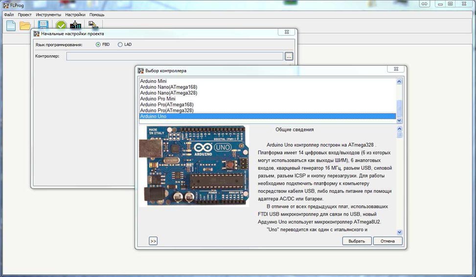
When you create a new project you will be prompted to choose the programming language in which you will create the project and the controller on which this project will be implemented.
Here is a list of Arduino boards supported by the program to date:
Arduino Duemilanove Arduino Leonardo Arduino Lilypad Arduino Mega 2560 Arduino Micro Arduino Mini Arduino Nano (ATmega168) Arduino Nano (ATmega328) Arduino Pro Mini Arduino Pro (ATmega168) Arduino Pro (ATmega328) Arduino Uno Intel-Galileo
Over time, as acquisitions, we plan to support boards based on the controllers STM.
A project in FL Prod is a set of circuit boards, each of which is assembled a complete module of the General scheme. For convenience, each card has the name and comments. As each charge can be minimized (to save space in the work area when the work is finished) and deploy. The red led in the name of the Board indicates that in the circuit Board there are errors.

The view window of the program in the FBD language.

Вид окна программы в режиме языка LAD.

In the right part of the working area place the library elements. In the diagram, the elements are transferred by simple drag and drop. By double clicking on the item will shows the information about it.
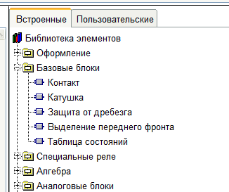
Here is a list of units currently available
FBD:
Базовые элементы
[XOR][AND][OR][Bounce]
Специальные блоки
[Scale]
Триггеры
[SR][TT][RS][Rtrig]
Таймеры
[Generator][Timer]
Счетчики
[Counter][SpeedCounter]
Математика
[SUM(+)][MUL(*)][SUB(-)][DIV(/)]Алгебра[SIN][COS][TAN][ABS][SQ][SQRT][MIN][MAX][POW][RANDOM]
Сравнение
[Comparator]
Com –порт
SendSendVariableReceiveVariable
Переключатель
[SWITCH][MUX][DMS]
Моторы
ServoMotorStepMotor
Часы реального времени
[Alarm][GetTime][SetTime]
Дисплеи
Дисплей на чипе НD44780Подсветка дисплея на чипе НD44780 I2CБлок декодирования семисегментного индикатора
Строки
Сложение строк
Датчики
[Ultrasonic HC-SR04][DHT11, DHT21, DHT22][DS18x2x][IR Ressive] [BMP-085]
SD карта
Запись переменной на SD картуВыгрузка файла с SD карты
Конвертация типов
Преобразование строкПреобразование Float в Integer
Микросхемы расширений
Расширитель выводов 74HC595
Операции с битами
ШифраторДешифраторЧтение битаЗапись бита
Разное
Матричная клавиатураПьезодинамик
EEPROM
Запись в EEPROMЧтение из EEPROM
Коммуникации
SendVariableFromCommunicationRessiveVariableFromCommunicationWebServerPageWebClient
[collapse]
LAD:
Базовые блоки
КонтактКатушкаЗащита от дребезгаВыделение переднего фронта
Специальные реле
Двустабильное релеРеле времениГенераторРеле сравнения
Алгебра
SINCOSTANABSMAXMINSQSQRTPOWRANDOM
Аналоговые блоки
МасштабированиеМатематикаСчетчикАналоговый переключательПереключатель много к одномуПереключатель один ко многимАналоговый вход контроллераАналоговый выход контроллераВход аналогового соединителяВыход аналогового соединителяСкоростной счетчик
CommPort
Передача в ComPortПередача переменной через Comm portПрием переменной через Comm port
Моторы
СервомоторШаговый двигатель
Часы реального времени
Получить данныеБудильникУстановка времени
Дисплеи
Дисплей на чипе HD44780Блок управления подсветкой дисплея на чипе HD4480 I2CБлок декодирования семисегментного индикатора
Строки
Сложение строк
Датчики
Ультразвуковой дальномер HC-SR04Датчик температуры и влажности DHT11 (DHT21, DHT22)Датчик температуры DS18x2xIR RessiveBMP-085
SD карта
Запись переменной на SD картуВыгрузка файла с SD карты
Конвертирование типов
Конвертация строкПреобразование Float в Integer
Микросхемы расширений
Расширитель выводов 74HC595
Операции с битами
ШифраторДешифраторЧтение битаЗапись бита
Разное
Матричная клавиатураПьезодинамик
EEPROM
Запись в EEPROMЧтение из EEPROM
Коммуникации
Блок отправки переменной через коммуникацииПрием переменной через коммуникацииСтраница Web сервераWeb клиент
[collapse]
Currently under development of functional units for working with triaxial gyro, luxometer, and other transducers and sensors. Work is also underway on the organization of data exchange via the radio channel and Wi-Fi. In future plans. development of SCADA system for the organization of the interface systems developed in the program FLProg on a personal computer or graphic displays.
The list of peripherals supported by the program, available here
For part of the equipment in the section of the site contains review articles that facilitate the understanding of its application in the program.
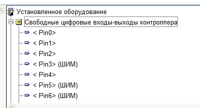
In the upper part of the working area is a list of tags (variables and inputs / outputs) (FBD) or installed equipment (LAD). Tags or equipment are transferred to the diagram by dragging and dropping.
In the upper part of the working area is a list of tags (variables and inputs / outputs) (FBD) or installed equipment (LAD). Tags or equipment are transferred to the diagram by dragging and dropping.For part of the equipment in the section of the site contains review articles that facilitate the understanding of its application in the program.

After completion of the project is its compilation. After compilation will automatically open the program “Arduino 1.5.7” with the loaded sketch of your project. In the “Arduino IDE 1.5.7” you will need to specify the number of the COM port that is connected to your controller, select it, and then pour in the sketch to the controller. Read more about “Arduino IDE 1.5.7” can be read on the website Arduino.ru.
Where to download FLProg?
On the downloads page.
You can download the program without registering on the website, but for registered users the functionality of the site significantly expands. Registration is very simple and requires only the confirmation email. No other data input is not required.
On the download page of the program always is available in two versions: installer and portable version that requires no installation. If possible, I also post the update file is significantly smaller, allowing you to upgrade from a previous version
flprog.ru
Подключение сервоприводов к Arduino
Сервопривод это точный исполнитель который получая на вход значение управляющего параметра стремится создать и поддерживать значение на выходе исполнительного элемента.Для подключения к контроллеру от сервопривода тянется 3 провода обжатых стандартным 3 пиновым разъемом с шагом 2.54мм . Цвета проводов могут варьироваться. Коричневый или черный – земля (GND), красный – плюс источника питания (VTG), оранжевый или белый – управляющий сигнал (SIG).
Подключение Серво :
У старых Ардуин, укомплектованных мегой 8, имеется всего три ШИМ вывода (digital 9,10,11), у Ардуин укомплектованных мегой 168 или 328 их 6 (digital 3,5,6,9,10,11). Семейство Arduino MEGA имеет на своем борту целых 14 ШИМ выводов.Мини сервы, потребляющие слабый ток, можно подключать напрямую к пинам Arduino.

Подключение мощных сервоприводов может вызвать большую просадку напряжения, контроллеру может не хватить питания, мега8 очень привередлива и из-за этого контроллер отключится. Так же на плате Arduino установлен маломощный стабилизатор не рассчитанный на потребление большого тока и чрезмерное потребление может перегреть его и повредить плату. Во избежание этого при использовании мощных серв, либо больше одной слабой, рекомендую подавать питание на сервопривод отдельно. Можно приобрести блок питания на 5 или 6 вольт, в зависимости от напряжения питания ваше сервы, либо поставить стабилизатор.

Как видно из рисунка необходима установка конденсаторов, можно и без них, но выходное напряжение будет не стабильным. Рекомендуемые номиналы конденсаторов: на входе 0.33 мкФ, на выходе 0.1 мкФ. Я всегда ставлю два по 100мкФ. Чем больше – тем лучше. И последнее и очень важное о чем стоит упомянуть так это то, что необходимо соединить земли источников питания.
 273 Comments: 9Publics: 291Registration: 04-02-2018
 flprog.ru
Programmers, as a first lesson it is customary to use “Hello World”, the programmers of the microcontroller to the led blinked, but the electricians and electronics engineers to collect the control diagram of the contactor. Since the primary users of the program just they are, assemble the first lesson will be just this scheme.
Standard circuit control contactor
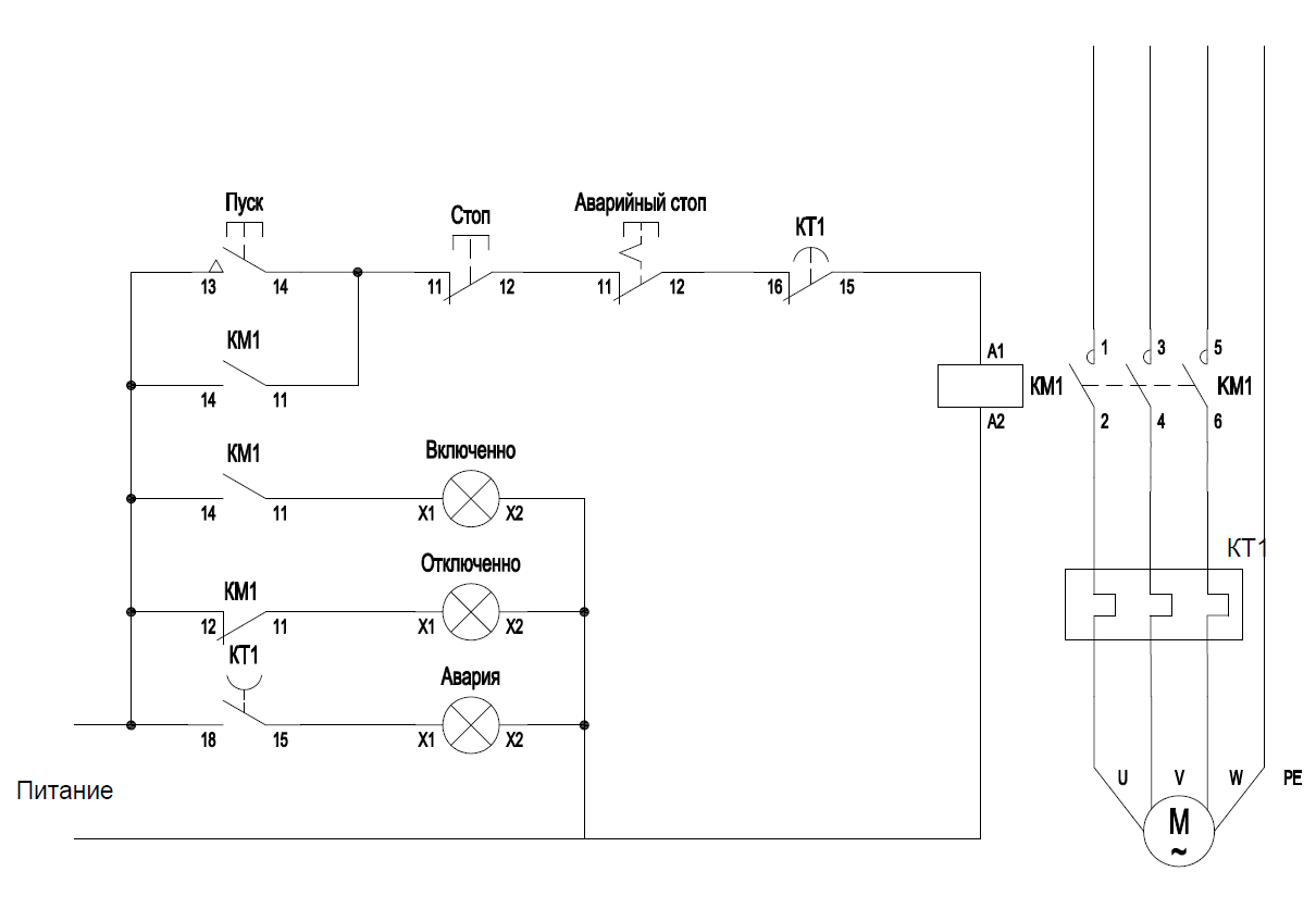
Replace flowchart by the controller Arduino. Let’s leave aside the issues of noise immunity and shielding. This topic is for a separate and very large conversation. Our goal is to create a program FLProg appropriate logic. Therefore, distribute the test connection diagram.

The role of the contactor in the test scheme performs led “Contactor”. Now try to program the controller.FLProg run the program, click “Create new project”.

Opens the selection window of the controller and the programming language of the project.
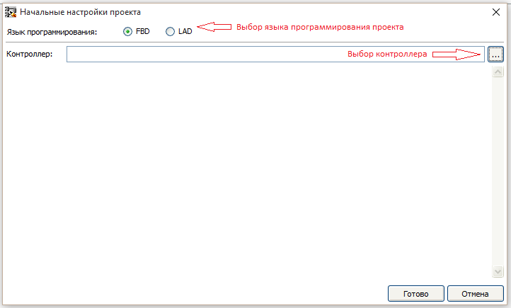
To create a project, you can use either of the two programming languages (FBD and LAD) are standards in programming industrial controllers. In this tutorial we will create projects in both languages.
Please note that after you create the project in one of the languages to change it is impossible!
Clicking the controller opens the appropriate window, which will be presented supported by the Board.
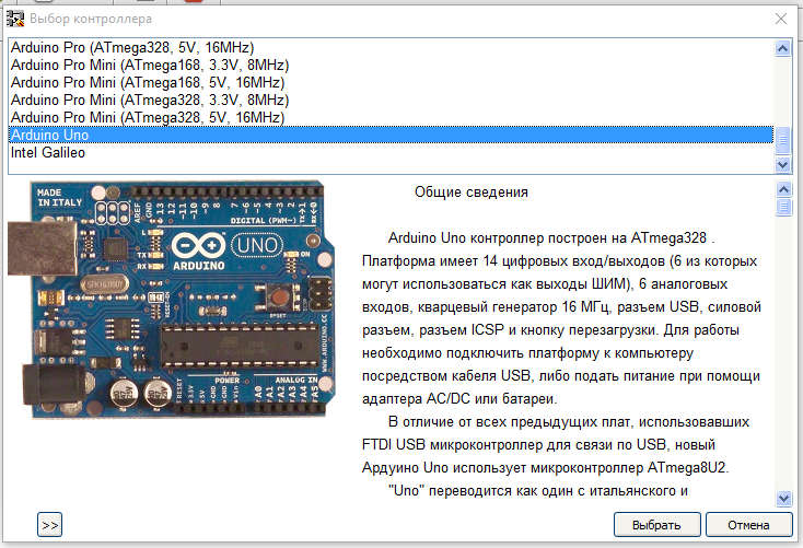 In this list select the desired controller.
Selected for a project controller to change at any time.
To begin, create a project in the language LAD.
Ladder Diagram (LD, LAD, RKS) – ladder (ladder) logic. The syntax of the language easy to replace logic circuits, made on relay technology. The language is aimed at automation technicians, working in industrial enterprises. Provides a visual logic interface controller to facilitate not only the task of actually programming and commissioning, but and fast Troubleshooting the plug-in to the controller hardware.A program in ladder logic is visual and intuitive electrical engineers graphical interface, representing the logical operations like electrical circuit closed and open contacts. The flow or absence of current in this circuit corresponds to the result of the logical operation (true if the current flows; false — if the current does not flow). The basic elements of language are the contacts that can be figuratively likened to a pair of relay contacts or buttons. Pair of contacts is identified with a Boolean variable, and the condition of this pair — with variable value.Vary normally closed and normally open contact elements that can be mapped with normally closed and normally open buttons in electrical circuits.
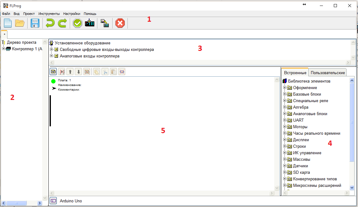
Working window of the program FLProg in FBD consists of several fields:
To start, pull out the diagram pane contacts button. This can be done in two ways.
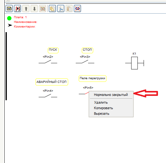
As a result, the scheme appears to HUGO (semi – graphical notation) of the contact. In the case of dragging it from the tree of the installed equipment, the contact will be immediately linked to a digital input / output Board. If the contact block was pulled from a library of elements, it will abstract a contact without any binding.
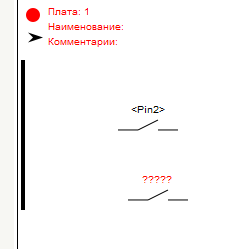
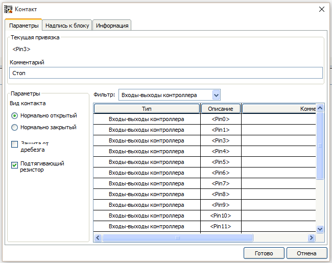
And in any case the contacts need to be parameterised. To do this, double-click on the contact. Opens the edit window of the block.

First and foremost, on the “Settings” tab you select a binding contact to the exit fee (if a contact is selected in the library blocks).Then new options appear. Protection “bounce” and “pull up resistor”. Since in accordance with the scheme of the button is connected to GND, put a tick “pull up resistor”. “Protection from bounce” can not install, in this scheme it is not necessary.
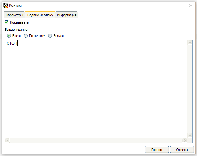
On the tab “Label to block” write the name of the button that would show it on the diagram.
On the tab “Information” you can view information about this device.

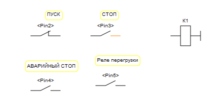
In the same way we take out the rest of the buttons and the contacts of the overload relay.

Then dragged from the block library device “Coil”. Also double click on it and opens the parameter adjustment of the coil.

Appointed by the coil of the intermediate relay K1, double-clicking on the corresponding item of the list.Now we need to set the status of the contacts.The program FLProg contact state corresponds to the level on the associated input card. If the input Board 0 – contacts are open if the 5V is shorted. Because the buttons in accordance with a scheme connected to GND and includes built-in pull-up resistors, when the closed button on the Board input will be 0, and when you let the button 5B. In accordance with these regulations put compliance contacts. This can be done in two ways.

You should get here is the status of the contacts (the opposite to the standard scheme for the previously described reason)
Well, now you can start to draw a diagram in accordance with the standard schema of the starter. Connections are drawn by pointing the cursor on the first output element, pressing the left button, and without releasing the button, the connection stretches until the second of the connected output. If when approaching the cursor to them that followed, connection the output is colored in orange; it’s a connection you can connect
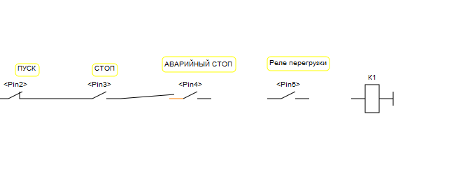
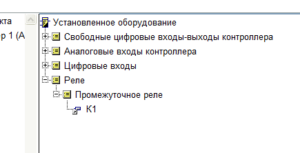
To create a block contact of the contactor, you can drag the contact K1 from the tree of the installed equipment at the scheme.
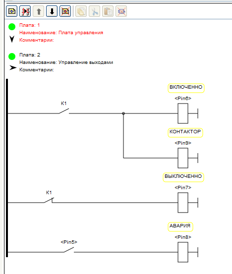
The result should turn out such a scheme. I think any electrician will understand her work (including invert state of contact inputs tied to the Arduino Board).
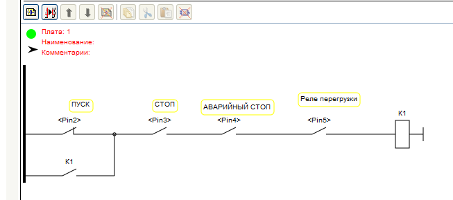
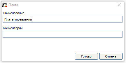
Thus, the first charge is finished. Let’s call it “control Board”. In order to assign a name to the PCB double-click on its header.

Opens a dialog to edit the header Board.
The green circle in the header indicates that the cost of correct and incorrect blocks on it. In the case of these units it will be red.Now create another payment, click on “Add adapter”

It will control the outputs of the Arduino Board. To do this, drag on second charge four reels from the library of blocks and tie them to the outputs of the Arduino Board. Must get this picture
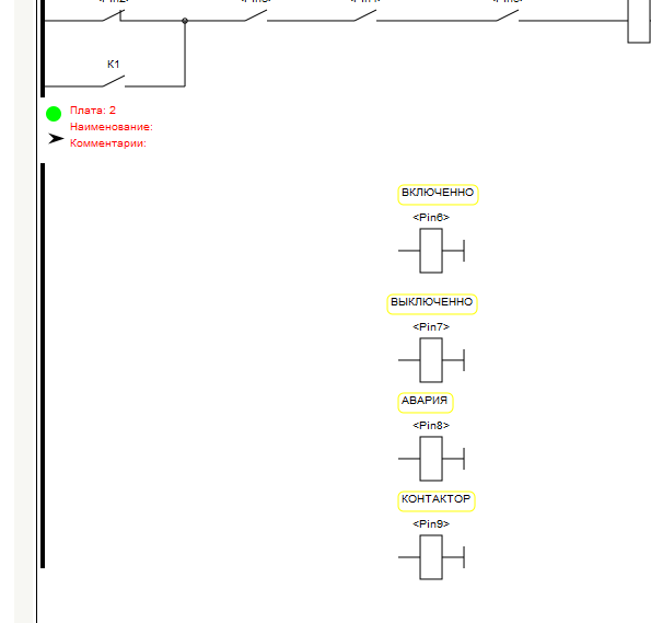
Coil with the associated pay outs relate to this: when you turn on coil in the project Board Arduino will be 5V when switching off 0Then dragged from the tree of installed equipment necessary contacts (the two contacts of the intermediate relays, contact input overload relay), and then draw the required circuit is called an “output Control”.
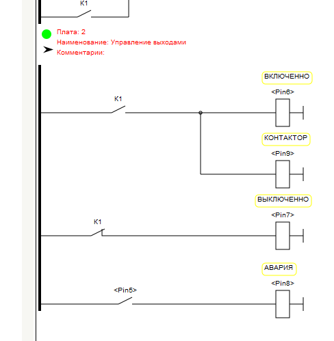
The arrow in the header of the circuit Board enables to minimize the cost, which saves space on the desktop and speed up the program with large circuits. When you click on the arrow Board or folds or unfolds.
The download to controller for both languages are the same, so we consider it at the end of the lesson, and until you create a similar project in FBD.
FBD (Function Block Diagram) – a graphical programming language standard IEC 61131-3. The program is formed from the list of circuits to be performed sequentially from top to bottom. When programming uses sets of library units. Block (element) — is a subroutine, function, or function block (AND, OR, NOT, triggers, timers, counters, blocks of analog signal processing, mathematical operations, etc.). Each individual chain is an expression that is composed graphically from the individual elements. To the output of the unit is connected the next block, forming a chain.Within the circuit blocks are executed in the order of their connection. The result of the calculation circuit written in an internal variable or output it to the controller.
Create a new project in FBD.
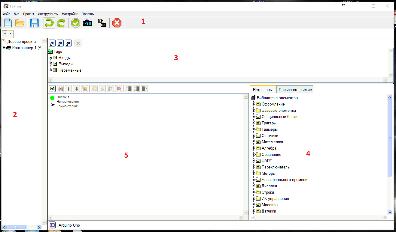
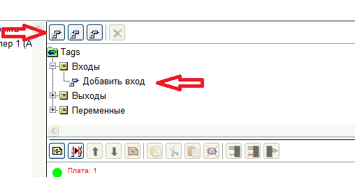
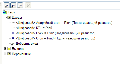
Fields 1, 2, 4, 5 in the program window are similar to those found in the language of the LAD. Field 3 here contains a tree of tags (inputs, outputs and variables). There are no pre-generated inputs, they must be created when needed. To create a new entry click “Add entry” or double-click on “Add input” in the tree tag.
A window will open create a sign
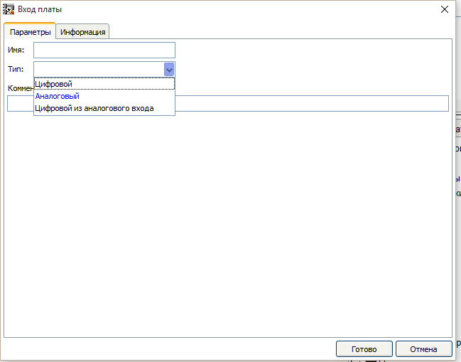
Choose digital, new options appear. Write the name, choose the right Arduino Board input and put a tick “Enable pull-up resistor”.

In the same way add all the required inputs
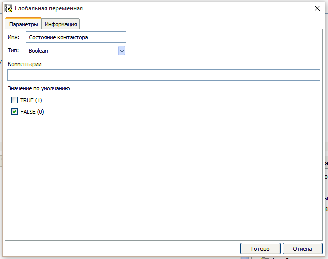
Then create a variable that is responsible for the condition of the contactor. To do this, either click on the button “Add variable” or double-click on the “Add variable” in the tree tag.

The configuration window of the variable

Select the variable type is Boolean and fill settings
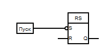
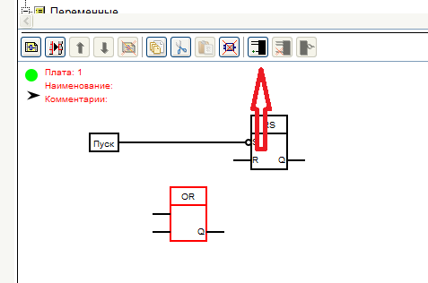
Units of input in FBD correspond to the real pay outs, as follows. When the real input is 0 – the output block is False, when the Board input 5B the output of block True.For memorizing the state of the contactor use the RS trigger. It is necessary to drag from the folder “Triggers” library units in the working area of the diagram.

RS-flip-flop, or SR-flip-flop — flip-flop, which retains its previous state with zero inputs and changes its output state when applying for one of its inputs units.When submitting units to the input S (from the English. Set — Set) the output state becomes equal to the logical unit. But when the supply unit to the input of R (from the English. Reset — reset) the output state becomes equal to a logical zero.When a logical zero at both inputs the output is kept the last state. When logical units on both inputs of in the case of the RS trigger output is set to logical zero, and in the case of SR trigger in the logical unit.
For that would turn on the contactor must submit to the S input, the input “start”. To do this, drag from the tree tag to the entry “START” in the workspace schema. If you remember that clicking start Board input a logical 0, it is clear that it is necessary to invert the signal from the button. To do this, move the cursor to the input S of the trigger and click the right mouse button. In the opened menu choose item “Invert”

Then connect the S input of the flip-flop output block input “start”. The establishment of the connection occurs, as well as in the language LAD.
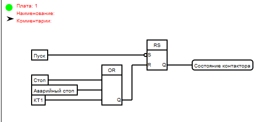
Stop contactor takes place if:Press “STOP” (log.1 block input “Stop” ) OR press “EMERGENCY STOP” (log.1 on the block of the input “Emergency stop” ) OR work out the thermal switch (log.1 block input “CP1” ). So we need the unit OR with three inputs.
Drag it from the library blocks folder “Base units”.
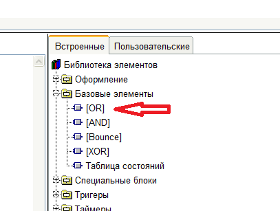
By default, a block OR two entrances. In order to add a third allocated block and click “Add entry”.
Transfer the inputs from the tree of tags and connect to the inputs of the OR block. And the output of the unit OR connected to the input R of the trigger.Then pick from the tree of the tag variable “State contactor” and a trigger output connected to the entrance of this variable. Must get this pattern:
This concludes the first charge and call her and LADе – “control Board”.Then create a new card and immediately call it the “output Control”.Next, create pay outs in accordance with the scheme. To do this, click on the button “Add output” length to double-click on the “Add output” in the tree tag. Outputs creating a digital type.
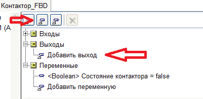
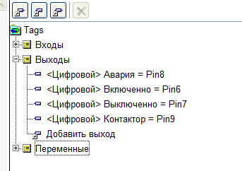
Drag on the second charge created outputs, input CP1 and the variable “State contactor” A
 LogoFlprog
File size: 174 KB
273 Comments: 9Publics: 291Registration: 04-02-2018
LogoFlprog
File size: 174 KB
273 Comments: 9Publics: 291Registration: 04-02-2018 flprog.ru

Приобрести можно в магазине - партнере проекта FastAVR со скидкой 10% ( Драйвер, двигатель с драйвером)
Шаговый двигатель 28BYJ-48 и его драйвер, работающем на основе микросхемы ULN2003A.
Шаговый двигатель 28BYJ-48 обладает хорошим крутящим моментом, хоть и заставить его вращаться быстро будет непросто. Подобные двигатели работают в вентиляторах и кондиционерах, поэтому они не так уж и дороги (хотя выглядят так массивно). При том, будучи устроенным гораздо проще, чем сервопривод, шаговый двигатель является очень надёжным и доступным устройством!
Также Вы можете посмотреть на драйвер. Именно это устройство передаёт команды от Вашей Arduino на сам двигатель! Чип ULN2003A, на основе которого построен драйвер, позволяет с помощью слабого тока микроконтроллера, такого как Arduino, управлять мощными нагрузками с током до 500 мА и напряжением до 50 В. Как раз такой нагрузкой и является двигатель.
Подключение шагового двигателя предельно понятно – на корпусе драйвера есть специальный разъём, куда необходимо вставить кабель от 28BYJ-48. Гораздо интереснее разбираться с самим драйвером! Четыре вывода In1, In2, In3 и In4 необходимо подключить к цифровым пинам Arduino – именно через них будет идти управление магнитами внутри двигателя. Обратите внимание, что в коде порядок этих пинов при подключении шаговика будет 1-3-2-4, что необходимо для правильной работы схемы. Далее, если Ваш мотор будет вибрировать, но не вращаться так, как Вы хотите, – практически наверняка проблема в очередности пинов. Также необходимо подключить “питание” и “землю” – для этого есть соответствующие пины “+” и “-” возле надписи “5-12V”. Шаговые двигатели обычно требуют довольно большого питания, поэтому дополнительно есть пины, рассчитанные на 12 Вольт и сейчас перекрытые маленьким пластиковым джампером. В идеале же стоит использовать отдельный источник питания!

Как мы уже говорили, шаговый двигатель вращается согласно последовательности, в которой включены его внутренние электромагниты. В нашем случае постоянно включены только две из четырёх катушек, и только состояние одной из этих катушек изменяется на следующем шаге. О том, какие катушки включены, говорят и горящие лампочки на плате драйвера.
elref.ru
Приобрести можно в магазине – партнере проекта FastAVR со скидкой 10% ( Драйвер, двигатель с драйвером)
Шаговый двигатель 28BYJ-48 и его драйвер, работающем на основе микросхемы ULN2003A.
Шаговый двигатель 28BYJ-48 обладает хорошим крутящим моментом, хоть и заставить его вращаться быстро будет непросто. Подобные двигатели работают в вентиляторах и кондиционерах, поэтому они не так уж и дороги (хотя выглядят так массивно). При том, будучи устроенным гораздо проще, чем сервопривод, шаговый двигатель является очень надёжным и доступным устройством!
Также Вы можете посмотреть на драйвер. Именно это устройство передаёт команды от Вашей Arduino на сам двигатель! Чип ULN2003A, на основе которого построен драйвер, позволяет с помощью слабого тока микроконтроллера, такого как Arduino, управлять мощными нагрузками с током до 500 мА и напряжением до 50 В. Как раз такой нагрузкой и является двигатель.
Подключение шагового двигателя предельно понятно – на корпусе драйвера есть специальный разъём, куда необходимо вставить кабель от 28BYJ-48. Гораздо интереснее разбираться с самим драйвером! Четыре вывода In1, In2, In3 и In4 необходимо подключить к цифровым пинам Arduino – именно через них будет идти управление магнитами внутри двигателя. Обратите внимание, что в коде порядок этих пинов при подключении шаговика будет 1-3-2-4, что необходимо для правильной работы схемы. Далее, если Ваш мотор будет вибрировать, но не вращаться так, как Вы хотите, – практически наверняка проблема в очередности пинов. Также необходимо подключить “питание” и “землю” – для этого есть соответствующие пины “+” и “-” возле надписи “5-12V”. Шаговые двигатели обычно требуют довольно большого питания, поэтому дополнительно есть пины, рассчитанные на 12 Вольт и сейчас перекрытые маленьким пластиковым джампером. В идеале же стоит использовать отдельный источник питания!

Как мы уже говорили, шаговый двигатель вращается согласно последовательности, в которой включены его внутренние электромагниты. В нашем случае постоянно включены только две из четырёх катушек, и только состояние одной из этих катушек изменяется на следующем шаге. О том, какие катушки включены, говорят и горящие лампочки на плате драйвера.
273 Comments: 9Publics: 291Registration: 04-02-2018 flprog.ru
Теперь небольшая предыстория. Один из пользователей программы обратился в фирму «Ноотехника» с предложением создать пользовательский блок (в то время в программе уже была такая возможность) для работы с производимым ими оборудованием через программу FLProg. Руководитель предприятия пошёл другим путём. Он связался со мной и предложил предоставить мне образцы своей продукции для интеграции их в программу. Изучив предложение, я согласился, поскольку на сайте была библиотека для работы с модулем передатчика, в наличии было хорошее описание, и проблем я не видел. Посылка пришла очень быстро (что странно для почты России) даже с учетом пересечения границы.Что пришло:
Модуль передатчика МТ1132

Модуль MT1132 предназначен для управления силовыми блоками системы nooLite с платформы Arduino, микроконтроллеров или ПК.Конструктивно модуль выполнен в виде печатной платы, на которой расположен управляющий контроллер и передатчик.Управление модулем осуществляется через последовательный интерфейс UART. Принятые по UART команды управления модуль передает на силовые блоки через встроенный радиопередатчик.
Силовой блок SD111-180

Радиоуправляемый светодиодный RGB контроллер (силовой блок) nooLite SD111-180 предназначен для управления светодиодной лентой на 12 В. Светодиодная лента может быть как трехцветная (RGB), так и одноцветная.
Силовой блок SU111-300

Силовой блок SU111-300 — это универсальный радиовыключатель, предназначенный для дистанционного включения/выключения освещения с возможность регулировки яркости для диммируемых источников света (лампы накаливания, светодиодные диммируемые лампы). Блок может работать в двух режимах: релейном и диммирования, зависящих от предполагаемого типа нагрузки. В релейном режиме SU111 300 способен работать с любым типом нагрузки.
Более подробную информацию об этих устройствах можно узнать на сайте производителя.
Блоки сделаны очень качественно. Подозреваю, что предприятие работает на базе какого – то бывшего советского предприятия, а в советские времена в Белоруссии производили хорошую технику. Хотя может я и ошибаюсь.
Оригинально реализована система включения привязки силовых блоков. Для включения этого режима необходимо сжать корпус в определённой точке, и сработает микропереключатель внутри. Но в инструкции это место показано достаточно чётко, так что я попал с первого раза.
Первое включение передатчика то же заставило немного понервничать. При подаче питания на плате ничего не засветилось, хотя светодиод на плате есть. Я привык, что индикация наличия питания есть на всех устройствах. На этом передатчике его нет. Я даже сначала решил, что плата не работает, и полез тестером мерить напряжения. Но все вроде в порядке. Тогда загрузил библиотеку с сайта, и начал пробовать примеры. Светодиод моргает при отправке команды. При этом и тут есть тонкость. Он моргает не при получении данных по UART, а именно при отправке команды в эфир. Эта особенность то же заставила понервничать. Уже при разработке компилятора внезапно перестали проходить команды на силовые блоки, и перестал моргать светодиод. Хотя я четко видел, что пакеты по UART уходят. Решил, что я всё-таки его спалил. Оказалась что ошибка в коде, и контрольная сумма, которая присутствует в пакете, у меня неправильно рассчитывалась. Соответственно передатчик этот пакет не принимал и команды не отправлял. После исправления кода, всё прекрасно заработало.
Теперь насчет библиотеки, которая лежит на сайте производителя. Первоначально я планировал использовать её. Но поковырявшись с ней, понял, что она меня не устраивает. Во первых она не поддерживает работу с контроллером светодиодной лены(SD111-180). Во вторых она не умеет управлять режимом диммирования для силового блока(SU111 300). Ну и напоследок она гвоздями прибита к SoftwareSerial. Это не всегда хорошо. Всё-таки в ряде случаев для экономии ресурсов лучше использовать аппаратный UART. Поэтому мне пришлось разрабатывать код самому (естественно подглядывая в реализацию библиотеки).
Во всём остальном это оборудование оставило очень приятное впечатление. Работает стабильно, возможностей много, качество на очень высоком уровне. По цене конечно выше чем привычное мне оборудование из Китая. Но в Китае аналогов пока нет (по крайней мере такого же комплекса я не нашёл), ну а по сравнению с дальним зарубежьем где производят подобные системы, цена даже очень привлекательна.
Ну а теперь посмотрим на реализацию управления передатчиком через программу FLProg.
Подключается передатчик к Arduino в соответствии со схемой.
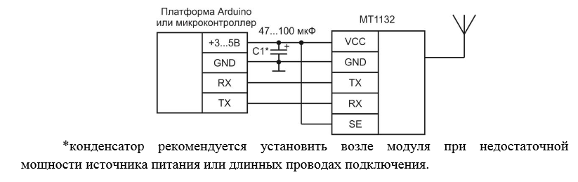
Соединение RX (Arduino) – TX(MT1132) можно не использовать, поскольку обратную связь от передатчика к контроллеру (подтверждение отправки команды) я не реализовывал. Исключение этой связи позволяет при использовании аппаратного UART не отключать передатчик при проливке контроллера.
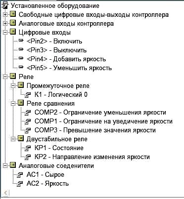
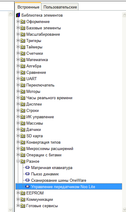
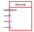
Для управления передатчиком в программе FLProg, в библиотеке элементов появился блок «Управление передатчиком Noo Lite» (папка «Разное»).

Отправка команды на передатчик происходит по переднему фронту импульса на входе «Send». Для каждой команды можно использовать отдельный блок, или команда может задаваться значением, подаваемым на вход «Comand».Как и все остальные этот блок настраивается с помощью редактора блоков (вызывается двойным кликом на блоке, перенесённом в рабочую область схемы).Если Вы параметрируете первый такой блок в схеме, то необходимо подключить новый передатчик.

При этом откроется окно подключения передатчика
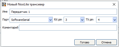
В этом окне необходимо задать имя передатчика и выбрать порт, к которому он подключен. В случае использования SoftwareSerial, так же необходимо выбрать пины для этого порта.После подключения передатчика необходимо установить канал, на котором команда будет передаваться.
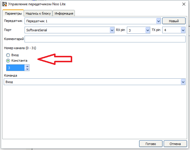
Канал можно задать как константой, итак и использовать для этого вход. Соответственно при использовании входа, канал можно изменять програмно.
Ну и напоследок выбираем отправляемую команду.
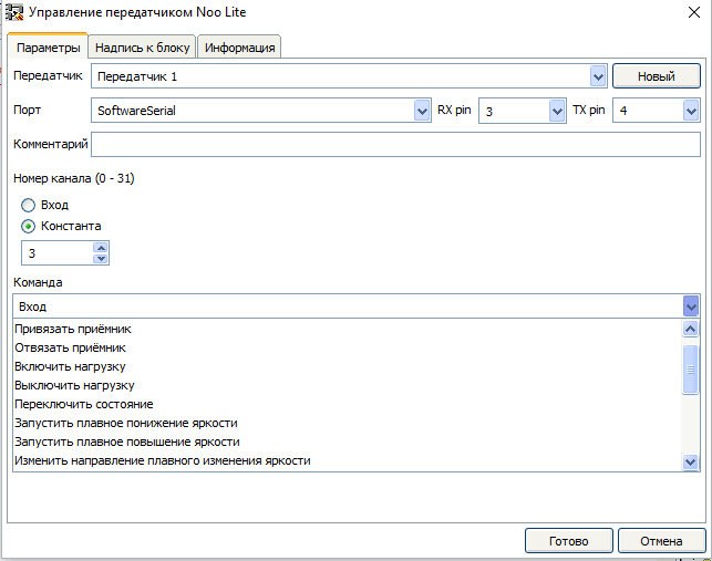
Список поддерживаемых команд:
Для выбора команды можно использовать и вход (в списке команд выбрать «Вход») и в этом случае в процессе выполнения программы можно изменять, команду подавая на вход «Comand» её номер.
Номера команд:
| 0 | Включить нагрузку |
| 1 | Запустить плавное понижение яркости |
| 2 | Выключить нагрузку |
| 3 | Запустить плавное повышение яркости |
| 4 | Переключить состояние |
| 5 | Изменить направление плавного изменения яркости |
| 7 | Установить сохранённое состояние |
| 8 | Запомнить состояние |
| 9 | Отвязать приёмник |
| 10 | Остановить плавное изменение яркости |
| 15 | Привязать приёмник |
| 16 | Включить плавный перебор цветов (только для контроллера LED ленты) |
| 17 | Переключить цвет (только для контроллера LED ленты) |
| 18 | Переключить режим работы (только для контроллера LED ленты) |
| 19 | Переключить скорость эффекта (только для контроллера LED ленты) |
Обратите внимание, что в этой таблице нет команд «Задать яркость (0 — 120)» и «Установить яркость для каждого канала (0-255) (только для контроллера LED ленты)». Для отправки этих команд необходимо использовать отдельный блок. Давайте рассмотрим эти команды поподробнее.
«Задать яркость (0 — 120)» — при выборе этой команды в редакторе блока появятся дополнительные параметры.
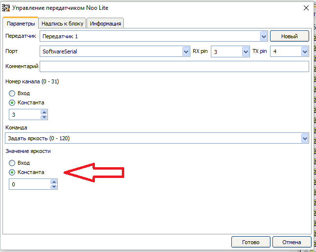
С помощью этих параметров можно задать значение яркости, передаваемое в команде как константу, или использовать вход. Во втором случае входа у блока появится вход «Value»

«Установить яркость для каждого канала (0-255) (только для контроллера LED ленты)» — при выборе этой команды в редакторе блока так — же появятся дополнительные параметры.
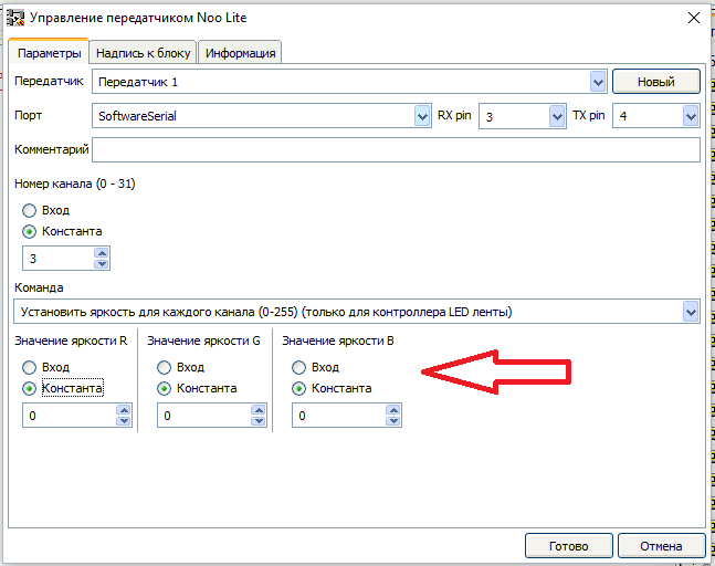
И так же как в предыдущей команде значение яркости для каждого канала можно задать как константой, так и использовать вход. У блока при этом появятся соответствующие входа – «R», «G», «B»
Ну, наверное, и всё, спасибо за внимание.
273 Comments: 9Publics: 291Registration: 04-02-2018 flprog.ru

Управление сервоприводом и шаговым двигателем в программе FLProg.
FLProg - Урок 9. Как подключить двигатели к Arduino . Ссылки на компоненты: Шаговый двигатель 28BYJ-48 с драйвером ULN2003...

Flprog Драйвер Шагового Двигателя ...

Flprog Драйвер Шагового Двигателя ...
Скетч код: http://arduino4life.ru/node/23 Этот видео урок про подключение биполярного шагового двигателя к arduino через...
Как подключить шаговый двигатель 28BYJ 48 с драйвером ULN2003 к Arduino при помощи FLProg. Подробности на сайте: http://arduinopro...
Описание процесса преобразования и программа для получения переменной из ШИМ Схема http://adf.ly/1k7UG1 Программа...
Как подключить серводвигатель к Arduino Ссылки на используемые компоненты: Ардуино Mega2560 Rev3 - http://ali.pub/ojxz9 ЖК-дис...
Драйвер двигателей L298N - Обзор, Тест, Подключение к Arduino *********** Драйвер двигателей: http://ali.pub/1a1zxx Драйвер двига...

Регулятор скорости для шарового двигателя. Для изготовления понадобится; Arduino UNO R3. Пяти вольтовый шаговый...

Программный код для управления створкой теплицы по температуре при помощи шагового мотора Код в flprog http://adf.l...
контроллер - http://ali.pub/1tzk0z кнопки выпуклые - http://ali.pub/1tzk3p Хотите оказать помощь в развитии канала или мастер...

Драйвер Шагового Двигателя L9110s ...
Вторая часть - https://youtu.be/QJ4NRZxYisI Теория, программирование и практика создание следящего шагового мотора и...
![ПОДКЛЮЧАЕМ ШАГОВЫЙ ДВИГАТЕЛЬ К ARDUINO [Уроки Ардуино #14]](/800/600/https/i.ytimg.com//vi/jJQwmnyfw5k/mqdefault.jpg)
В уроке использовались следующие компоненты: 1) Плата Arduino Uno + USB-кабель: http://ali.pub/24xb2q 2) Перемычки, 40 шт: http://ali.pu...
скачать пример можно тут: https://yadi.sk/d/dQ4a4tN8xwuoD а библиотеку тут: https://github.com/adafruit/AccelStepper.
http://www.pcbway.com - PCBWay изготовление печатных плат. Тема урока: управление шаговым двигателем и схема подключен...

Драйвер Мотора Arduino ...
Подробное руководство по подключению шагового двигателя 28BYJ-48 к Arduino с помощью драйвера ULN2003. Пример и подро...
ИК Управление на Arduino в программ Flprog. Управляем нагрузками при помощи любого инфракрасного пульта управлен...


В этом видео мы с вам продолжим работу над станком Постройка ЧПУ фрезера в мебельной мастерской. Несколько...
Шаговый двигатель и arduino. Подробности на http://justforduino.blogspot.ru/2015/09/arduino.html.
Подключение шагового двигателя. Поворот вала двигателя на разные углы в одном направлении. Составление...
В этом уроке рассмотрим как на базе ардуино уно можно управлять электродвигателем с помощью джойстика....

Кнопки +100 RPM -100 RPM Start/stop.
В этом видео производится запуск шагового двигателя без маркировки и с неизвестными параметрами, использу...
Как подключить шаговый двигатель 28BYJ 48. Ссылки на используемые компоненты: Шаговый двигатель 28BYJ-48 с драйвер...
Подключение Драйвера ШД DM542 к Ардуино Уно Статья: http://test-kb.ru/Robots.htm Группа в ВК: https://vk.com/cybsys Скетч в группе....
Датчик для нового проекта . Ссылка на товар https://goo.gl/ClXvjd.
Установка блоков пользователей в программе Flprog Это предварительное видео перед видео про PID регулятор...

Нижний подогрев - техническое задание, схема соединений и используемые модули и компоненты. Огромная благо...
Зарядное устройство на Ардуино с функциями - Авто заряд, Замер ёмкости АКБ, Десульфатор Схемы Скетчи: https://yad...

FLProg - Урок 16. Энкодер - Как создать пользовательский блок. Ссылки на используемые компоненты: ЖК-дисплей...

L293d Драйвер Шагового Двигателя ...

Управление Драйвером Шагового Двигателя Arduino ...

Нижний подогрев - реализация в программе FLProg. Огромная благодарность автору программы Сергею Глушенко,...
В этом видео я расскажу о подключении шагового двигателя к Ардуино. О электрических принципиальных схемах...
lcd nokia 5110: http://ali.pub/18jqhl Модуль для лазера: http://ali.pub/18jqv0 Easydriver для шаговых двигателей: http://ali.pub/18jqzo Драйвер с...
crack the sims 3 1.67.2 le3256 atualizacao madeira de lei stardew valley qual o melhor launcher de minecraft sony d2114 reset como instalar o corel x8 no windows 7 como descobrir o endereco mac do celular de outra pessoa root moto g1 5.1 action mediafire como baixar dragon block c 1.7.10
debojj.net